
Inhaltsverzeichnis
E-602 (E44)
Allwellenempfänger 44 (All Wave Receiver 44), E44; developed and produced by Autophon AG, Solothurn.
As a successor to the E39 receiver, which still used a technology with plug-in coil sets and a calibrated logging scale, Autophon started to develop a receiver with a turret tuner with directly switchable wavebands and a calibrated dial, which allowed the frequency to be read directly from the dial.
This receiver has been equipped with battery valves: it mainly used the battery heated pentode valve D1F, which was available in sufficient numbers even during the later years in WWII. The receiver has been ordered from the KTA (Federal war technology department) in 1944, but the sets were available only in 1945. Until 1951, a number of 143 sets has been made at Autophon plant in Solothurn.
Technical Data
- Frequency range: 100 kHz - 37,5 MHz in eight frequency ranges, turret tuner for band selection
- Analog dial, nonlinear
Power Supply

- Mains: 110, 125, 145, 160, 220, 250 V with matching power supply E44Z
- Accumulator / Batteries: 6,3 V
Dimensions
- Receiver case E44: 400 x 320 x 310 mm, 23.75 kg
- Mains power supply and audio amplifier E44Z: 400 x 200 x 310 mm, 18.8 kg
Accessories
- Standard antenna is a long wire antenna
- Antenna transformer AT44

Operation
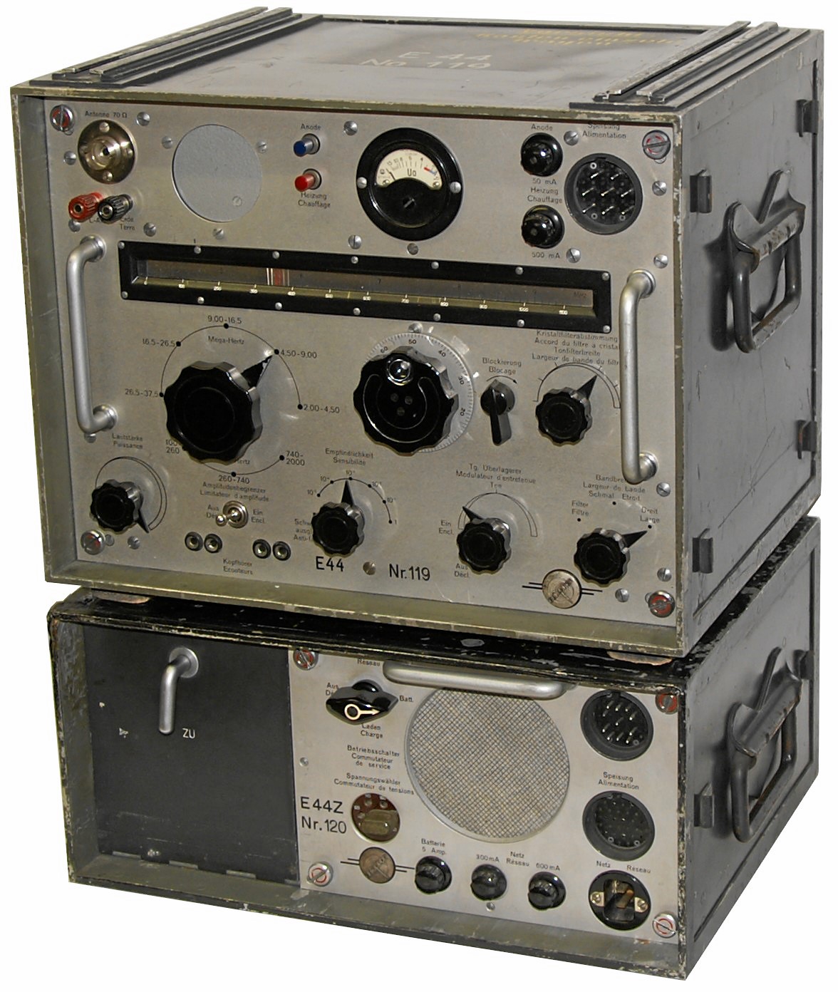
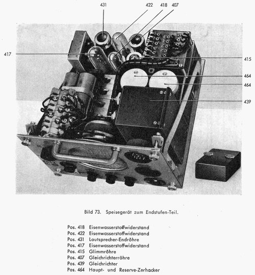
The receiving equipment consists of the Receiver E44 in one case / container and the EZ44 in a second case, this one containing a separate mains power supply and an integrated audio stage (with a EBL21 AF tube) and speaker.
Both sets are connected by a heavy multipole cable. The receiver itself has a weight of 23.75 kg and the power supply / AF amplifier case another 18.8 kg. Usually some 18 kg of accumulators came together with this set.
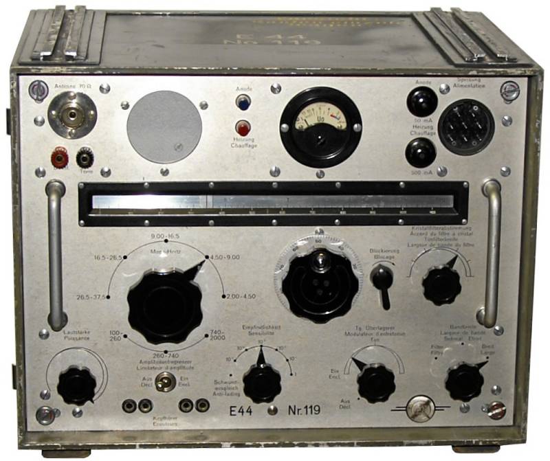
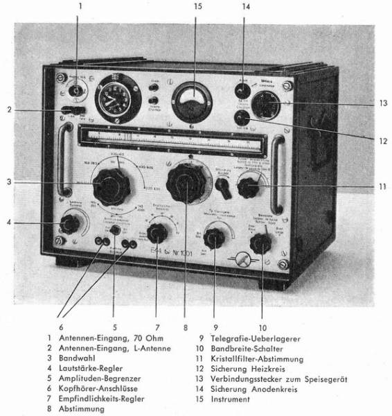
The front panel is divided in two sections by the horizontal linear dial of the turret tuning arrangement. Above the dial, You find from the left hand the coaxial antenna connector and the sockets for connecting longwire antenna and earth, then the clock (many of these neat Swiss clocks have been taken away by station personnel when these receivers have been taken out of duty), and the signal strength meter. This can be switched to indicate the heaters and plate / B+ voltages. At the right upper corner, you find the socket for the multipole cable (caution: the receiver is almost useless without this cable) and some fuses.
Underneath the frequency dial, you find the rotary band switch operating the turret tuner - find the corresponding dial in the dial window - and at the right hand the main tuning knob with a mechanical blocking arrangement. In a row of controls below, you find from the left the volume control („Lautstärke“ or „Puissance“ yes, in Switzerland we use both languages german and french), the mains switch, the AGC/RF gain control, the BFO control for CW reception, the selectivity switch activating the wide 7,6 kHz and the narrow 3 kHz IF filters, as well as the narrower crystal filter, the crystal filter tuning control („Kristallfilterabstimmung“) will move the passband of the crystal filter to reject unwanted signals from adjacent channels.
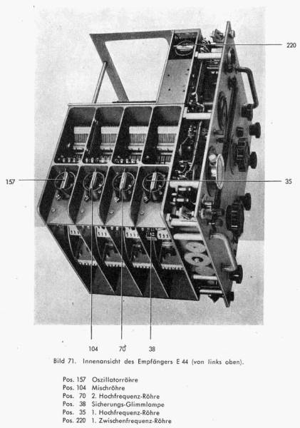
The single conversion set with two HF- and another two AF- amplifier stages is working with an intermediate frequency of 75 kHz in the ranges below 2 MHz and with an intermediate frequency of 1,6 MHz on the higher frequency bands.
A similar variant of this receiver, the E45, has been used as Airraid Warning Receiver by the Airforce and Anti-Aircraft-Troops, another mains operated variant using common valves has been produced under the E-52 designation and has been in use with Swiss PTT and Agence France Press.
There have been only very few sets made of a VHF-variant E46.
Technical Principle
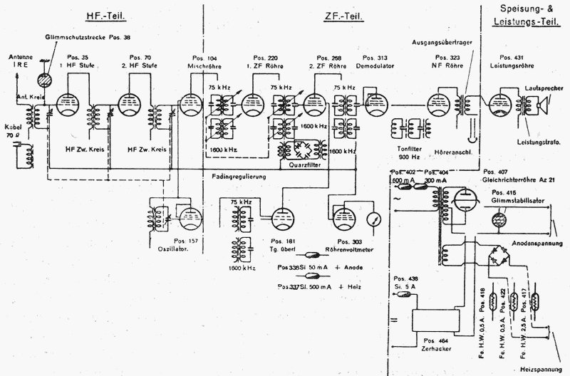
The antenna signal has to pass two RF preamplifier stages (D1F); on frequency ranges below 2 MHz, it is converted to an intermediate frequency of 75 kHz and in the ranges above 2 MHz to an IF of 1600 kHz in the mixer stage (D1F). This is followed by two IF amplifier stages (D1F, D1F). After having passed the crystal filter (active on frerquencies above 2 MHz), the signal is demodulated (D1F and fed to the audio preamplifier (D1F), it's output is sufficient for headphones operation. The audio final stage with a (EBL21) and the speaker are located in the power supply cabinet.
For CW and single sideband reception, the signal of the BFO (D1F) is fed to the signal before demodulation.
Valve setup
The receiver itself uses only battery valves of the type D1F, only the final audio amplifier stage in the power supply cabinet uses a EBL21.
Development
Field use
In the years 1944/45, a total of 143 receivers have been built.

