
Inhaltsverzeichnis
SE-211: TLA (Tragbar Leicht Artillerie, "Portable Light Artillery")
Tragbar leichte Funkstation der Artillerie (TLA), SE-211; developed by Telefunken Zürich.
In 1935, a in those days very modern Telefunken station was evaluated as a replacement of the obsolete radio material from the twenties. A case containing the transceiver, an additional case with the necessary batteries and a pedal generator completed the „Portable Light radio station“, which was in fact „portable“ with a total weight of 78 kg… During the years of the Second World War, this radio station carried the main burden of radio communication in the Swiss army. For use of the field and fortress artillery, in 1940 a variant of the TL station was ordered with a different frequency range, it was delivered to the troops from 1942 and later replaced by the K1A replaced.
Technical Data
- Frequency range: 2 - 3.333 MHz, analog dial, ca. 5 kHz accuracy
Power Supply
- Accumulator / Batteries: Accumulator 6 V for heaters; three plate batteries of 60 V each
- Generator: Pedal generator TG85 Scintilla
When the TLA was introduced, the mains power supply NG-TL (120, 145, 220, 250 V) from Zellweger, Uster was already available.
Dimensions
, Kiste")
- Apparatus Case (Transmitter): 405 x 490 x 217 mm, kg
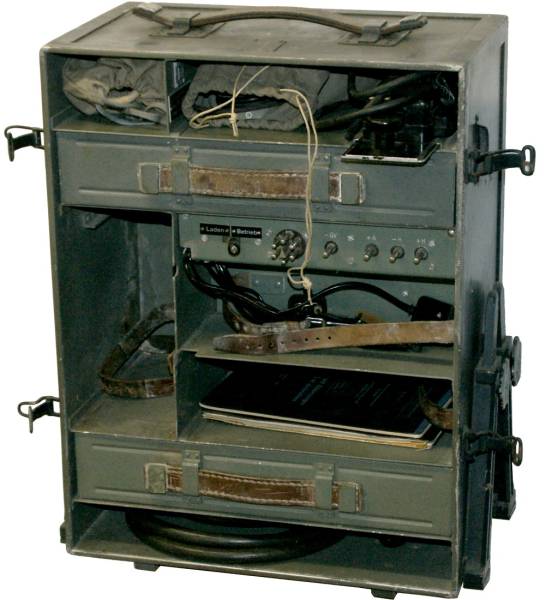
- Battery Case (Accumulator, batteries and accumulator charger): 405 x 490 x 217 mm, kg
- Treadmill generator: 300 x 300 x 860 mm, kg
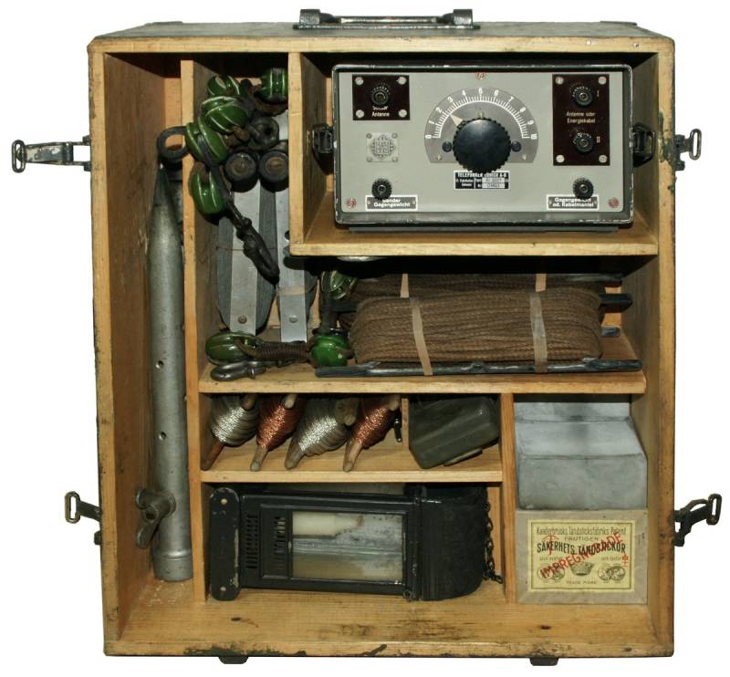
- Supplementary Case (antenna material, matching unit)
- Mains power supply (NG-TL): 380 x 570 x 317 mm, kg
Accessories
- Standard antenna was a 16 m L-antenna erected between two poles and a counterpoise.
- Long distance antenna: an alternative to the standard antenna was the long distance antenna with a length of 27 m.

Operation
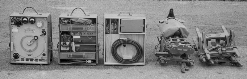
The „Portable Light Artillery radio station“ or „TLA“ is an early portable wireless set, which is „portable“ in the sense of the word: it is possible to be carried around. With the transceiver, the battery power supply, pedal generator or mains power supply unit, the supplementary case with accessories and matching antenna masts needs 4 man to carry the loads of 19 - 26.5 kg. In the manual, there is comprehensive information on how the station can be transported on skis, on horseback or on a canadian sled.
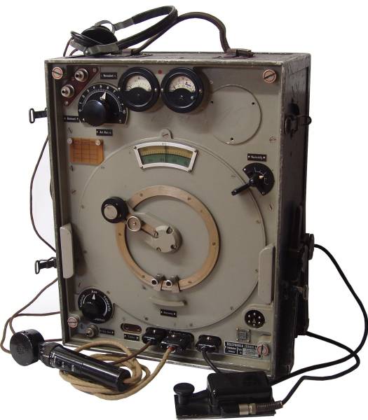
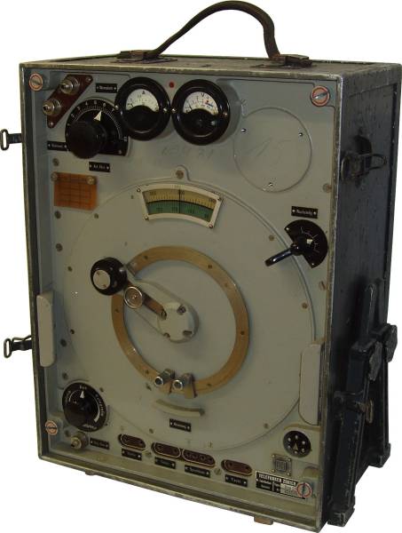
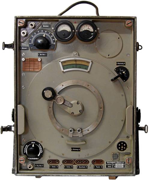
 The transceiver is referred to in the technical manual as „apparatus case“, the metal-clad box is equipped with a removable lid, a carrying strap on the top and adjustable „extendable“ feet, all coables are led out at the front panel.
By loosening the four red-marked screws, the chassis can be pulled out of the box; on the back the chassis, the tubes are now accessible, also the slider controls for the adjustment of the valve heaters voltage of the transmitter and receiver heating circuit (4 V), which need to be adjusted after each change of valves or hydrogen sulfide stabilizers.
First, all station components must be connected with the cables: the pedal generator is connected with the „machine cable“ to the battery case. The „apparatus cable“ connects the battery case to the transmitter. The station may only be operated with the 6 Volt NiFe battery (or a replacement) in place (even if the power supply unit is connected), as the accumulator serves for buffering and voltage peaks are avoided.
When the switch on the battery case is in the „Operation“position, the transmitter and receiver are ready for use, in the position „charging“ the transmitter is switched off, but the heaters accumulator is charged with a higher current.
All accessories and the machine and apparatus cables as well as spare tubes are stored in the battery box.
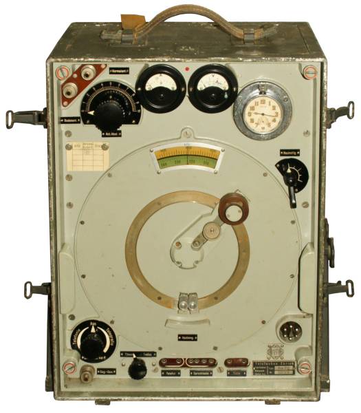
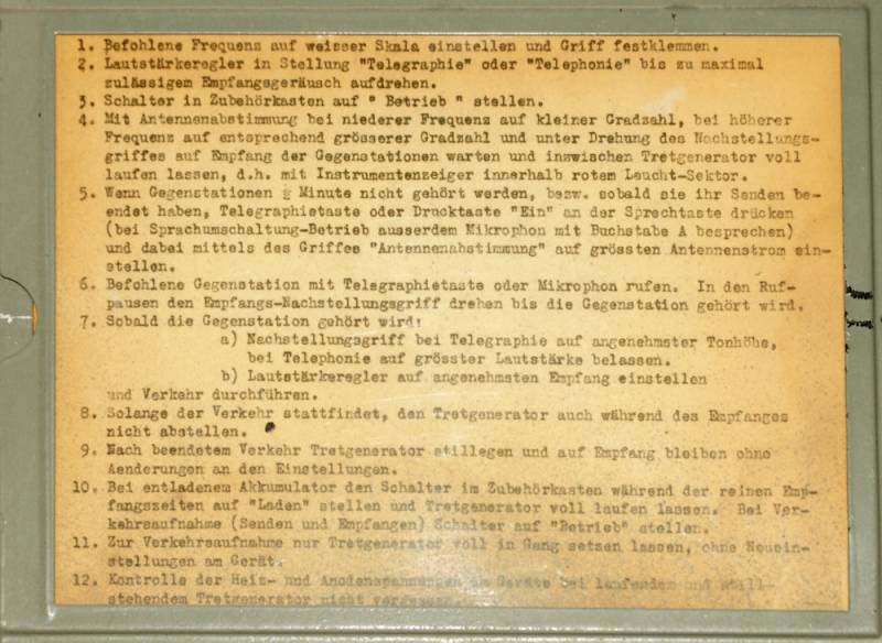
 After the necessary voltages have been applied, the radio set is switched on with the „Telephony“ - „Off“ - „Telegraphy“ mode switch; the maximum volume is reached at both end stops of the control. The right meter indicates the valve heating voltage, which should read 4V; when the small blue button is pressed, the plate voltage of 120-180 V is displayed.
With the very characteristic tuning lever, the frequency can directly be read from the dial window (in contrast to earlier sets, Telefunken not only provided a 0-100 dial, but for the first time a calibrated frequency dial). Fine tuning is possible by turning the knob on the end of the lever. The control „reception adjustment“ can shift the frequency by +/- 10 to 30 kHz. There are two mechanical locks to block the tuning lever on two frequencies, to allow the rapid change between two operating frequencies, like two simple mechanical „presets“.
After connecting the antenna and ground / counterpoise, the transceiver is set to the „Telegraphy“ position, the transmitter is keyed and the antenna tuning control is set to maximum reading of the antenna current meter.
In the „Telephony“ position, the transmit/receive switching is operated automatically in the „Sprachumschaltung“ position on the microphone (in this case, a VOX circuit was already implemented in a thirties radio set) or in the „Handumschaltung“ position using the OFF / ON pushbuttons.
Technical principle
 Transmit mode : the rf signal from the oscillator tube (RS242) - the tuning capacitor of the transmitting and receiving circuit are on the same axis and are mechanically coupled - is fed to the transmitter output stage (with two valves RS242) and from there via a variometer to the antenna output („Standard antenna “). Over a capacitor, it is fed to the „Bodenantenne“ connectors for the counterweight. A hot wire instrument indicates the RF current and must be tuned to maximum.
From the microphone, the AF signal is amplified (V4, RE084) and fed to the AF output stage. In telegraphy, this valve acts as tone generator for the sidetone. An amplifier tube (V5, RE084) is used for transmit / receive switching, in receive mode, a negative grid voltage of -65 V blocks the transmitter driver and output stages. Another amplifier tube (V6, RE084) is used for the VOX circuit, the voice-activated transceiver switching.
 Reception mode : the received signal passes through the common tuned transmitter-output and receiver input circuit to the RF amplifier stage (RES094) and is mixed in the oscillator / mixer valve V8 to the intermediate frequency of 870 kHz. After two IF amplifier stages (two RES094 each), the signal is fed to the regenerative detector stage for further amplification and demodulation (also RES094). In telephony operation, the anode voltage is reduced so that no oscillations can occur; in the telegraphy mode, the anode voltage is increased so that the regenerative circuit oscillates and CW emissions are audible. In the AF amplifie stage, the signal is amplified for headphones operation.
The power supply is very sophisticated. In reception mode, the receiver is supplied by the 6 Volt NiFe heaters accumulator and three plate batteries of 60 V each in the „battery case“.
As soon as the pedal generator is activated, a relay circuit in the battery case switches to generator power. The heaters accumulator acts in buffer mode and continues to heat the receiver valves. The receiver gets its plate voltage directly from the pedal generator, the transmitter circuit gets the heating and plate voltages from the generator. In mode switch position „operation“, sending and receiving is possible, in the position „charging“, the transmitter is switched off, the receiver remains operational and the battery is charged with an increased charging current of 1 Amp.
The voltages from the pedal generator, heaters voltage 8.5 V and plate voltage of 330 V and the negative grid voltage are reduced by FeH stabilisers to the operating voltages of the transceiver. The treadmill has to be turned with 58 - 62 tours, the instrument on the treadmill generator displays the correct turning speed.
Valve Lyaout
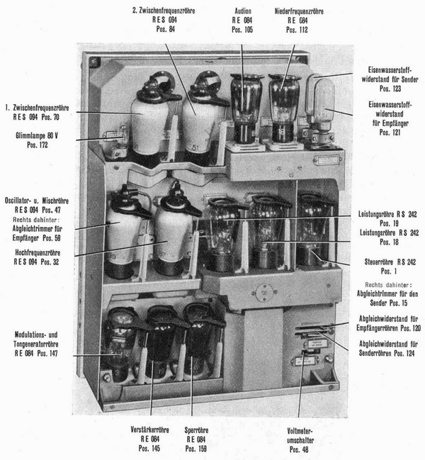 Transmitter: V1 (RS242, driver valce and oscillator; V2, V3 ([de:RS242]], transmitter output stage; V4 (RE084, modulation / audio generator valve); V5 (RE084, amplifier transmit / receive switch); V6 (RE084, voice operated switching (VOX);
Receiver: V7 (RES094, RF amplifier), V8 (RES094, oscillator / mixer); V9, V10 (two RES094, 1st and 2nd IF stage); V11 (RES094, regenerative detector) and V12 (RES094, AF amplifier).
Development
In the year 1935, the wireless station Telefunken Stat 272 Bs has been evaluated by the Swiss Army as a possible successor of the very outdated Swiss Army wireless equipment dating from the twenties.
 In 1931, Telefunken did develop a portable wireless set with 5 Watts output power, consisting of the 5W-transmitter Spez 469 Bs and the receiver Spez 445 Bs, both portable „backpack“ sets, the whole station was known as Kleinfunkgeraet a or Fu 9 . The German engineers preferred separate receivers and transmitters in these years.
A similar set with a combined transceiver in one „backpack“ was the 15 Watts transceiver Sendeempfaenger SE469A, Telefunken designation Stat 272 Bs. In Switzerland, an export variant of the Stat 272 was introduced as Stat. 1002 Bs covering 3 - 5 MHz, consisting of the transceiver Ase 211, battery case Spez 992 Bs and pedal generator. It was introduced with the troops from 1935 - 1946 and got the designation „Tragbar Leicht / TL“.
 At the request of the artillery, the marine band variant „TLA“ with a frequency range 2,0 - 3,33 MHz was developed. This set, the Telefunken Stat. 1011 Bs, consisting of Transceiver Ase 3017, battery case and pedal generator, was acquired for the artillery units 1942 / 1944 and got the designation TLA or SE-211.
At the time of the introduction in 1942, the mains power supply NG-TL was already available.
As early as 1947, the artillery stations were replaced in the field artillery by the wireless set REX. In 1951, the TLA station got the new designation SE-211, the TLA was liquidated in 1961.
Field Use
The station SE469A resp. Stat 1011Bs was developed by Telefunken Berlin, the sets were built by Telefunken Zurich; 588 units of the TLA stations were ordered at a price of 8,300.- Fr. and delivered to the artillery units in 1942/46.
A little later, the TLA was replaced by the radio set REX in the field artillery units, the TLA thus had only a very short service time.


