
Inhaltsverzeichnis
SE-406
Motorized shortwave station SE-406 or Telefunken Stat 1125B; manufactured by Telefunken - Albiswerke, Zürich.
Only Telefunken Zürich sent in a project on a call for projects for a high power shortwave radio station in 1949. In 1954, two prototypes of the radio station SE-406 were operational, a preliminary series of 15 stations was constructed for troop trials.
Following the great success of the development of the Zellweger single-sideband station SE-222, with which single-sideband technology gave nationwide coverage with relatively low transmitter power, no further SE-406 stations were procured.

Technical data
Power Supply
The station can be powered from mains or from a petrol generator:
- Mains: The station can be powered with 500 V or 3×380 V AC by means of mains transformer P1432.
- Generator: Petrol operated generator 400 V, 50 Hz, 7.5 kVA
The power supply of the station takes up a larger part in the technical manual. In the Ap 3060 power supply unit, the necessary voltages are fed to the individual units. A three-phase AC source (mains supply or petrol generator) can be connected to the power supply G 4017, mains current 220 V 800 W or a 220 V generator can be connected directly to the power distribution unit. The AC transformer P 1432 is used to transform the three-phase voltage from 500 V to the required voltages of 380/220 V. With the switching unit Ap 3072, the three-phase generator can be started or stopped from the operating room, a rectifier Ms 434 is used to charge the accumulators for vehicle lighting and reception only while the transmitter is not operational.
Dimensions
- Station vehicle 631 x 215 x 360 cm, 7887 kg
Accessories
- Two rod antennas for reception and one rod antenna for transmission are be used as standard antennas.
- Alternatively, an umbrella antenna can be set up for transmission.
- Transmitting and receiving operation is also possible via a dipole antenna, which has a length of 2 x 20 m on the lower frequencies and 2 x 10 m on the higher frequencies.
- Automatic antenna tuner Ap 3073: the output of the transmitter with an impedance of 70 ohms is adapted to antennas with different impedances, automatic „presets“ for the pre-tuned crystal controlled operating frequencies.
- Ap 3075 switching unit
- with the remote control Ap 3076 the station can be remote operated. It comes with a microphone amplifier and modulator oscillator tube. A microphone or microtel, a morse key or a Moser-Baer high speed telegrapy system graph or an ETK teleprinter can be connected.
Station equipment
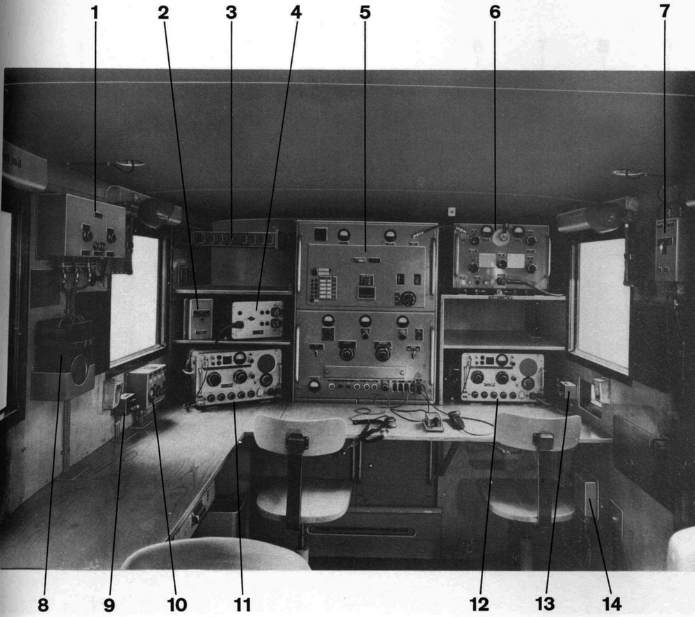
The shortwave station SE-406 is constructed on a truck chassis Saurer 2CM, it is divided to a radio room with the transmitter and two receivers and a operation room with the ETK teleprinter and the TC53 cipher machine for encrypted radiotelegraphy.
The Transmitter Ap 3062, the automatic Antenna tuner Ap 3063 with five preset frequencies and two Autophon E-627 receivers are located in the front part of the radio room.
 The transmitter Ap 3062 (5) has a design of a frame with four racks, the low-voltage rack (No. 4, 43 kg), high-voltage rack (No.5, 62 kg), the keying and modulation rack (No.2, 58 kg) and the transmitter rack (No.1, 36 kg). The racks can be pulled out like drawers for small service work or completely removed from the frame for more complex repairs.
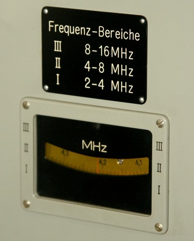
The transmitter is a plate modulated three stage transmitter, it can be tuned in the 2 - 16 MHz frequency range (range I: 2-4 / II: 4-8 / III: 8-16 MHz) or can be crystal controlled on five fixed channels. The transmitter is equipped with US tubes and has an output power of 400 W in the modes telegraphy A1A, modulated telegraphy A2A and telephony A3E, with an additional frequency shift keying unit, F2B for radioteletype operation is possible.
The semi-automatic antenna tuner (6) can be pre-tuned to the five crystal controlled frequencies; when the transmitter is used with it's variable oscillator, the antenna tuner must be tuned manually.
 Two receivers Autophon E-627 (11,12) are used as standard receivers; they can also be operated from the vehicle battery by means of a converter.
In the SE-406 station, newly developed radio teletype technology was fitted. The 14 segment teleprinter ETK together with the ciphering machine TC53 from E. Gretener AG can be used for encrypted radioteletype operation.
Technical principle
The design of the transmitter closely follows the design of the BC-610 transmitter which was used in the SM46, similar U.S. tubes were used.
 In the keying and modulator rack, the keying circuit (V53-V55) is used to supply the necessary voltages to to drive the driver and separation stage in the transmitter. The transmit / receive relay R1 is activated and the automatic switching from receiver to transmitter antennas in the antenna switching unit is triggered.
In telephony mode, the microphone voltage is amplified in the microphone amplifier tube V56 (6SJ7) and is fed to the audio amplifier tube V57a (6SN7, one system), when the microphone button is pressed. Teletype traffic is automatically interrupted via R5 and the grid bias voltage of the transmitter stage ist set to the value for AM operation.
In CW mode (A1), the keying relay R6 is addressed directly, with „Telegraphy modulated“ (A2), a tone oscillator using valve V52a (6SL7, one system) is activated and the oscillator signal is fed to the audio amplifier V51b (6SN7) and the phase inversion / amplifier stage V57b to drive the modulation amplifier.
For teletype operation, the AF signal of the ETK or the keying tone from the remote control is also fed to the keying amplifier (V52b, V51a).
The modulation amplifier consists of five stages: first the microphone or teletype signal is amplified (V57a (6SN7, one system), via the phase inversion / amplifier stage V57b, the signal is amplified in the first (V59, V60; two 6SK7) and the second push-pull amplifier stage V61, V62 (two 6L6). The push-pull final stage V63, V64 (4-125A) is only keyed in in the telephony and modulated telegraphy modes (R1) and is used to amplify the signal to drive the transmitter output stage via modulation of the anodes and grids of the final tubes.
The radio frequency is processed in the transmitter rack. The oscillator V201 (6L6) can be operated either variable or crystal controlled, five fixed frequencies can be selected with pushbuttons.
Next is the intermediate stage V202 (807): here the RF signal is simply amplified (range I), the frequency is doubled in frequency range II or tripled in range III.
In the transmitter final stage , the two final tubes V251, V252 (each 4-125A) are plate modulated with the signal of the modulation amplifier (V63, V64). With a switch on the modulator rack, the transmitter output can be reduced to 1/10 or 1/100. All transmitter stages are tuned with variometers.
In the Antenna tuner Ap 3073, the settings for five operating frequencies can be mechanically preset. With each frequency change, the antenna tuning is adjusted accordingly with motors. In the sixth position „without preset frequencies“ all lever systems are in neutral position and the tuning can be done by hand.
The antenna switching unit allows to connect the corresponding antennas to the two receivers, the main receiver (Ap 3074) and the auxiliary receiver (Ap 3064). The receiving antennas are earthed during transmission to prevent overloading of the sensitive receiver input stages.
Valve layout
Transmitter: V302-304 (5T4, low voltage rectifier); V401-404 (3B25, high-voltage rectifier); V51 (6SN7, audio and keying amplifier), V52 (6SL7, audio oscillator and keying amplifier), V53 (6H6, blocking / rectifier tube), V54 (807, keying tube), V55 (6H6, double blocking tube), V56 (6SJ7, microphone amplifier tube), V57 (6SN7, audio amplifier), V58 (6H6, amplitude limiter tube); V59, V60 (two 6SK7, push-pull amplifier); V61, V62 (two 6L6, push-pull amplifier tubes); V63, V64 (two 4-125A, push-pull final tubes); V201 (6L6, RF control stage tube); V202 (807, RF isolation tube); V251, V252 (two 4-125A RF final tubes); V203, V204 (two 0D3, stabilizer tubes).
Development
Only Telefunken responded to a call for proposals for a high power shortwave station. Finally, from the Stat. 1125B only a preliminary series of 15 stations was purchased, these stations were delivered in 1952/55 and were in use by the troops from 1953. The stations were operated by signalmen from Fk Kp 25 for command traffic between the Army HQ and the Army field corps.
 Increasingly, radio teletype became standard operation mode. With the ETK, the single-tone combination teleprinter made by Gretener AG together with the Telecrypto 53 encrypted teletype operation was possible. However, encrypted messaging suffered from the fact, that the cipher machines at the transmitter and receiver sites fell out of synchronization due to fading. Even with a single omitted character, the telegram could no longer be deciphered. This situation only improved with the use of the KFF58 with the built-in automatic synchronization.
Field use
The SE-406 station remained in use with the FunkerKp 25 until 1970 and was assigned to Landsturm signal companies until it was definitely withdrawn in 1980.


